Overview
VCON is a framework for remote (OTA) firmware updates and remote serial monitor, for a wide range of microcontrollers. VCON framework consists of two parts:
- A pre-built firmware for the ESP32 / ESP32C3 device
- A device management cloud (public at https://dash.vcon.io or private).

Any ESP32 / ESP32C3 device or module can be used. Flashing VCON pre-built firmware turns that device into a remote programmer and serial monitor. It can be registered on the management cloud, and be controlled remotely via GUI or the REST API. Once ESP32 is wired to the external device, that external device can be re-programmed over the secure REST API. An external, target device is called a "Host".
In addition to the OTA wiring, VCON module can be wired to the Host's UART. In this case, VCON module could be configured to act as a network bridge - either in transparent, or non-transparent mode:
- In trasparent mode, everything that Host MCU prints to the UART, VCON forwards to the server of your choice, MQTT or Websocket. Everything that VCON receives from the server, VCON writes to the MCU's UART. This enables bi-directional communication, where Host MCU "thinks" it talks to the UART where in fact it talks to the remote server of your choice - e.g. AWS IoT, or Azure, or your private MQTT server.
- In non-transparent mode, Host MCU can exchange JSON-RPC commands with the VCON shield and access a wide range of functionality - call external REST services, manage files, etc. Also, it can export RPC services itself, and VCON shield bridges those services to the REST API. This way, it is easy to create custom management interface to communicate with your MCU via familiar, secure REST API.
Supported targets
The following list shows target devices that can be reflashed by the current version of VCON firmware. Please contact us if you'd like to support your architecture of choice:
- ST Microelectronics STM32 G0, G4, L0, L1, L4, F0, F1, F2, F3, F4, F7, H7
- Microchip SAMD21, SAMD5x, SAME5x
- Microchip ATMEGA328, ATMEGA128
- Raspberry PI RP2040
- Texas Instruments TM4C
NOTE: UART bridging works on all architectures, not just on those listed above.
Recommended hardware
Any ESP32 / ESP32C3 device or module can be used as a VCON module. Some of our customers integrate ESP32 modules into their own PCB. Some use existing development boards available on the market. The choice is yours. Below we list only some of the options we think are worth noting, with our subjective opinion on the best applicable use case.
| Name | Image | Pros | Cons | Buy |
|---|---|---|---|---|
| ESP32C3 XIAO | 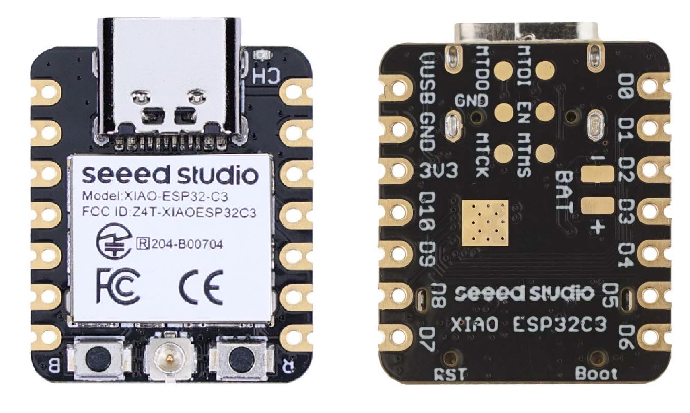 |
Very small form factor Reset button Inexpensive (about 5$) Surface-mountable |
No onboard antenna No status LED |
Digikey |
| Beetle ESP32C3 |  |
Small form factor Status LED |
No reset button Not SMT |
DFRobot |
| ESP32C3-Mini | 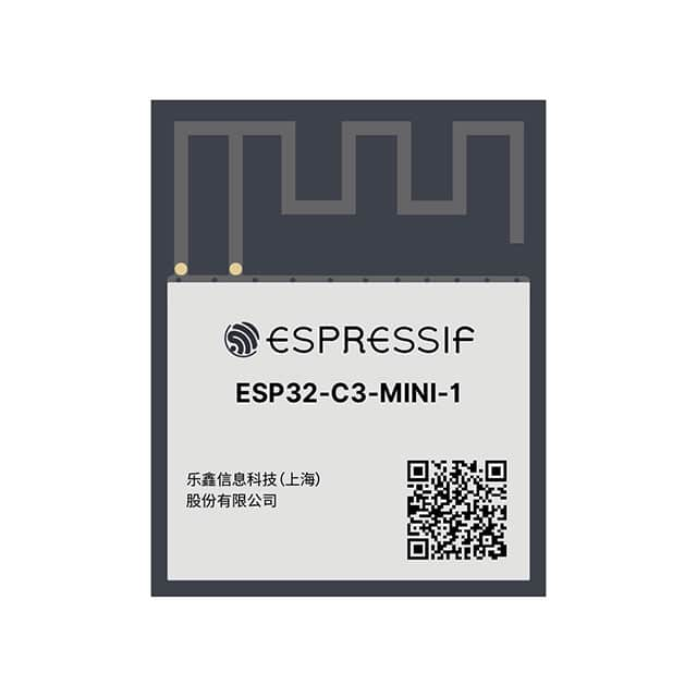 |
Cheap (< $2) Onboard antenna |
Cannot be used standalone | Digikey |
| Adafruit AirLift |  |
Compact Surface mountable Status LED |
No USB power No reset button |
Adafruit |
Downloads
esputilopen source ESP32 flashing / configuration utility (github repository)- esputil_macos - MacOS binary. Right click, "Save as"
esputil, thenchmod 0755 esputil - esputil_linux - Linux binary. Right click, "Save as"
esputil, thenchmod 0755 esputil - esputil.exe - Windows binary. Right click, "Save as"
esputil.exe
- esputil_macos - MacOS binary. Right click, "Save as"
- "Full" Firmware for initial flashing
- esp32c3.hex - for ESP32C3. Right click, "Save as"
vcon.hex - esp32.hex - for ESP32. Right click, "Save as"
vcon.hex
- esp32c3.hex - for ESP32C3. Right click, "Save as"
- "App" Firmware update
- esp32c3.bin - for ESP32C3. Right click, "Save as"
vcon.bin - esp32.bin - for ESP32. Right click, "Save as"
vcon.bin
- esp32c3.bin - for ESP32C3. Right click, "Save as"
- version.json - the latest firmware version
- CHANGELOG - firmware change log
NOTE: The difference between the "full" and "update" firmwares is that the "full" firmware contains the bootloader, the partition table, and the VCON app. The "update" firmware contains only VCON app. To update a production VCON module, use the "update" firmware.
User Guide
Module flashing
- Connect your ESP32 device hardware to the workstation. It should be accessible
via a serial port
COMPORT. On Windows, it isCOMn, likeCOM3,COM4, ... - open Windows' device manager to double-check. On Linux, it is usually/dev/ttyUSBnor/dev/ttyACMn. On Mac, it is usually/dev/cu.usbXXXX - Download an open-source
esputiltool for your OS:- esputil_macos for MacOS. Right click, "Save as"
esputil, thenchmod 0755 esputil - esputil_linux for Linux. Right click, "Save as"
esputil, thenchmod 0755 esputil - esputil.exe for Windows. Right click, "Save as"
esputil.exe
- esputil_macos for MacOS. Right click, "Save as"
- Download VCON firmware
- esp32c3.hex - for ESP32C3. Right click, "Save as"
vcon.hex - esp32.hex - for ESP32. Right click, "Save as"
vcon.hex
- esp32c3.hex - for ESP32C3. Right click, "Save as"
- Start command prompt (or terminal on Mac/Linux). Run the following:
Note: for ESP32C3 boards, you might need to specify an extra argument for flash parameters,cd DIRECTORY_WITH_DOWNLOADED_FILES ./esputil -p COMPORT flash vcon.hex-fp 0x22f. The most common parameters are-fp 0x220. For more options, see https://github.com/cpq/esputil#flash-parameters.
Module registration
This section describes how to configure network on a recently flashed ESP32 device, and how to register it on the https://dash.vcon.io cloud. There are two methods - one is using CLI (command line interface) over the USB connection, and another is using a Web UI app which works over Bluetooth.
CLI method
Run the following command to see module's debug logs:
esputil -p COMPORT monitor
You should see debug logs appearing. Press "enter" once to trigger command-line mode. You should see this:
Entering CLI mode, log output suspended. CLI commands:
  set PATH VALUE	Set config PATH to VALUE
  call NAME ARGS	Call RPC function NAME
  cat FILE		Show file contents
  reset			Reset to factory defaults
  reboot		Reboot device
  <enter>		Exit CLI mode, resume logs
Enter the following commands, line by line, terminating by single "enter":
set $.wifi.sta.ssid "YOUR_WIFI_NAME"
set $.wifi.sta.pass "YOUR_WIFI_PASSWORD"
set $.dash.pass "DEVICE_CLOUD_PASSWORD"
reboot
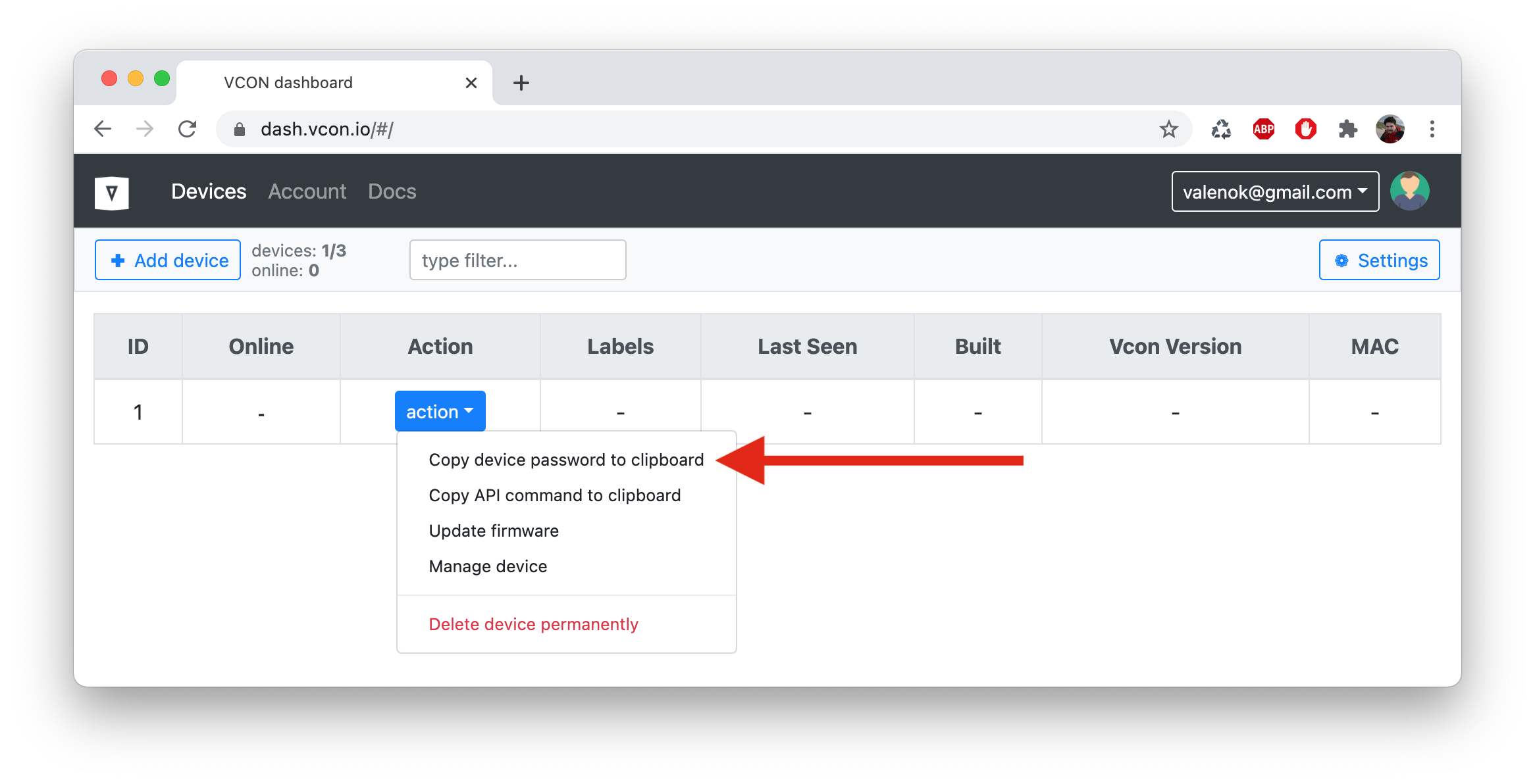
Note the double quotes! To get a DEVICE_CLOUD_PASSWORD, login to
https://dash.vcon.io. Click on "add device" to add a new device. Click on
"action" button. Click on "Copy device password to clipboard:
Web UI method
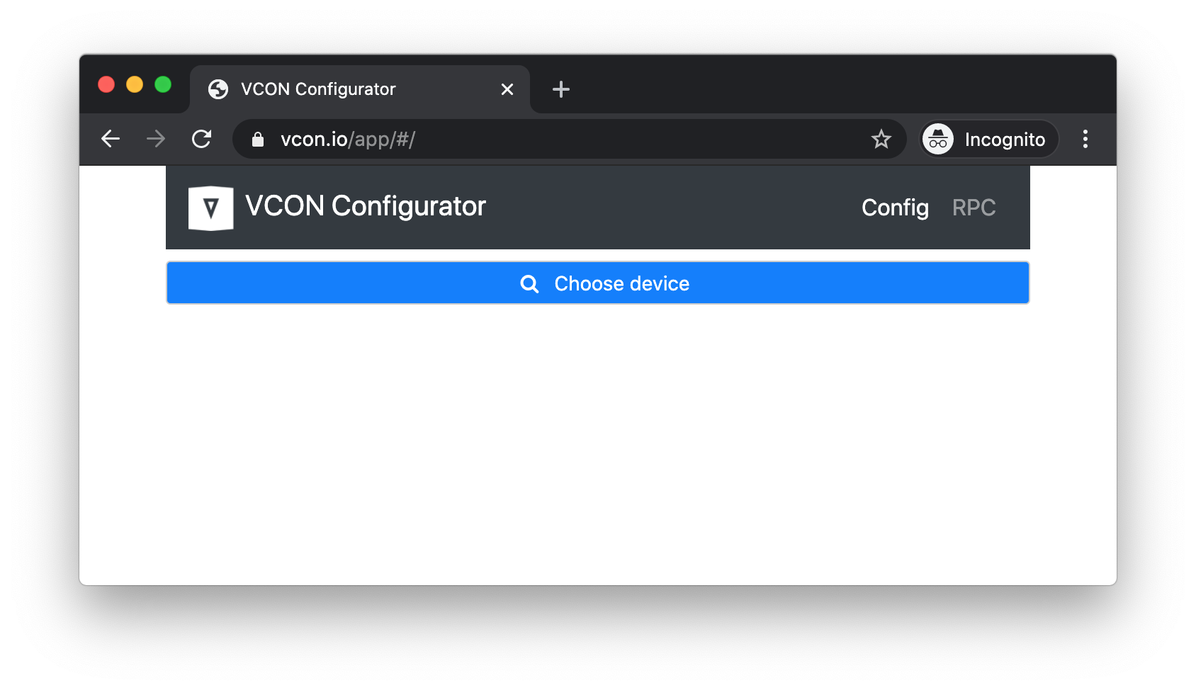
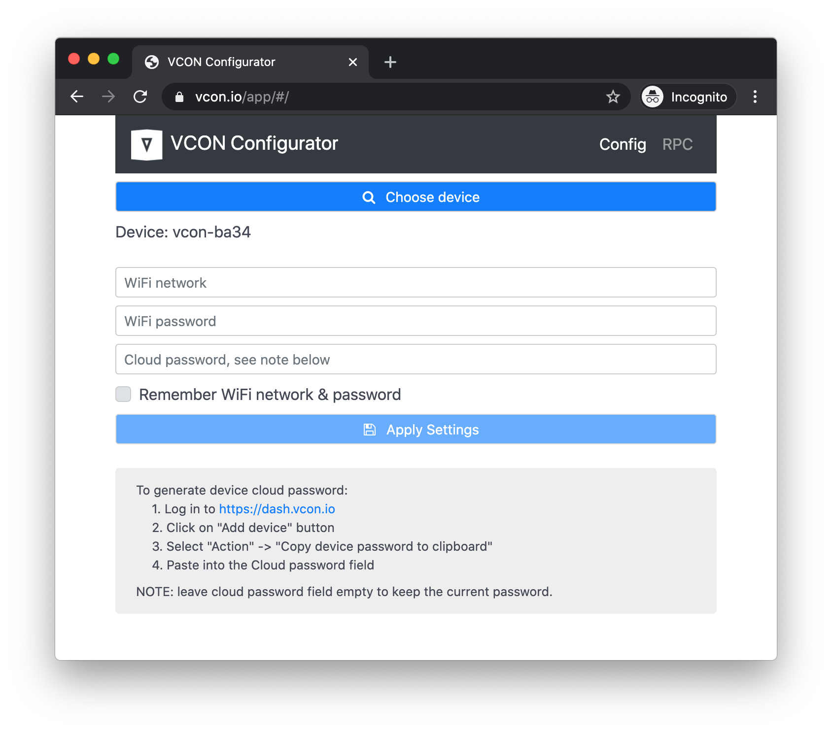
Open https://vcon.io/app/ in any Bluetooth-enabled browser, like Google Chrome or Microsoft Edge. Click on "Choose device" button:
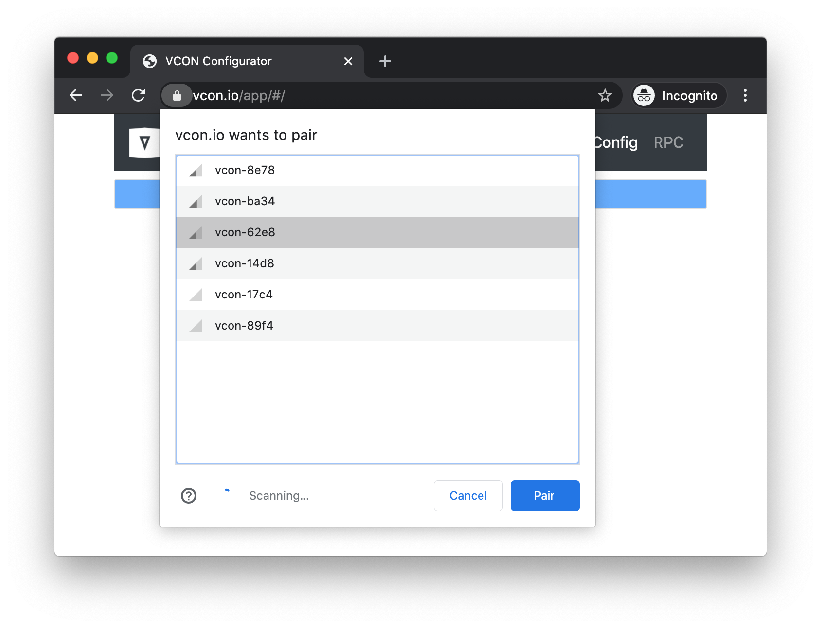
Select a device and click "Pair":
Login to https://dash.vcon.io. Each connected OTA shield must have an associated "cloud device" with unique access key (password). Click on "add device" to add a new device. Click on "action" button. Click on "Copy device password to clipboard:
Switch back to the configuration app. Fill in WiFi network name, WiFi password, device password and save settings:
Your device on a dashboard should become online:
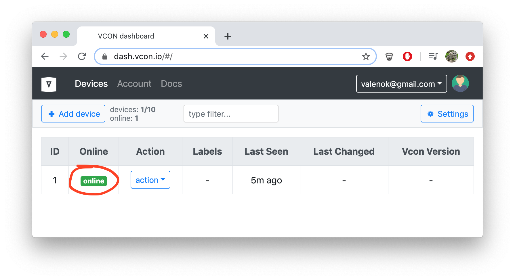
After WiFi and cloud credentials are set and device is rebooted, your device should become online:
Congratulations! Now ESP32 module can be controlled remotely. The next step is to wire an external microcontroller to it.
Module-to-device wiring
In order to wire ESP32 module to your target (Host) device, both programming pins, and UART pins should be connected together.
Programming pins depend on the programming method. ARM-based targets use SWD programming method, which uses two pins: SWDIO and SWDCLK. Some targets, for example STM32, support reprogramming via a serial bootloader. That method requires four pins: UART RX, UART TX, RESET, and BOOT0. ATMEGA targets use SPI-based programming, which uses three pins: MISO, MOSI, and CLK.
To wire UART pins, select any two available ESP32 pins and wire them to the target's UART RX and TX pins.
After physical wiring us done, change ESP32 configuration to reflect the wiring. The configuration can be changed via the UI, or via the API. In the examples below, both methods are shown.
PICO-W5500-EVB
- VCON module: ESP32C3 XIAO
- Target (Host) board: W5500-EVB-PICO

In this setup, it is ESP32C3 that powers both boards over USB. After the setup is done, it could the vica versa: the RPI board can power both.
Configuration using GUI
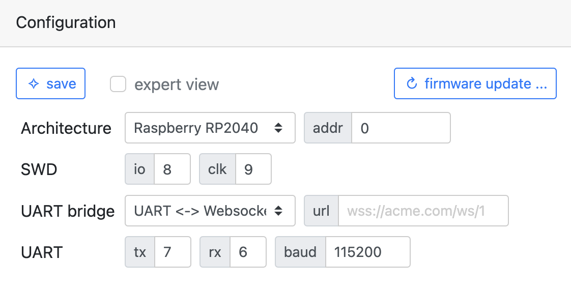
Once wiring is done, go to https://dash.vcon.io and select "action" → "Manage device" to configure the Host. This loads device management console with several different sections. Now we're interested in "Configuration" section. Change values to make it look like this and hit "save":
Configuration using API
The following console command performs the same setup as the GUI method above:
curl -su :API_KEY https://dash.vcon.io/api/v3/devices/ID/rpc/config.set \
  -d '{"config":{"host":{"arch":400,"mode":3,"uart":{"rx":6,"tx":7},"swd":{"io":8,"clk":9}}},"save":true,"reboot":500}'
In the command above, API_KEY is a cloud authentication key. It could be
copied from the UI dashboard. ID is the actual ID you're working with. It
can be taken from the UI dashboard.
See Configuration Reference for a detailed description of all configurable parameters.
STM32 BluePill

Configuration using GUI
Once wiring is done, go to https://dash.vcon.io and select "action" → "Manage device" to configure the Host. This loads device management console with several different sections. Now we're interested in "Configuration" section. Change values to make it look like this and hit "save":
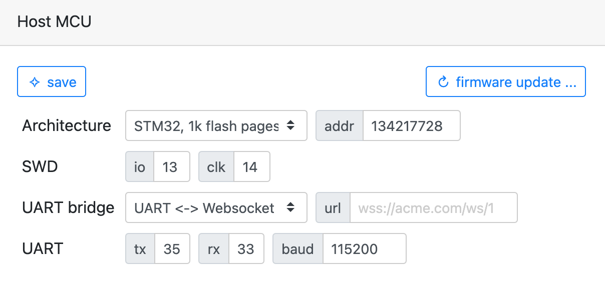
Configuration using API
The following console command performs the same setup as the GUI method above:
curl -su :API_KEY https://dash.vcon.io/api/v3/devices/ID/rpc/config.set \
  -d '{"config":{"host":{"arch":200,"mode":3,"uart":{"rx":33,"tx":35},"swd":{"io":13,"clk":14}}},"save":true,"reboot":500}'
In the command above, API_KEY is a cloud authentication key. It could be
copied from the UI dashboard. ID is the actual ID you're working with. It
can be taken from the UI dashboard.
See Configuration Reference for a detailed description of all configurable parameters.
Adafruit ItsyBitsy M4

Configuration using GUI
Once wiring is done, go to https://dash.vcon.io and select "action" → "Manage device" to configure the Host. This loads device management console with several different sections. Now we're interested in "Configuration" section. Change values to make it look like this and hit "save":
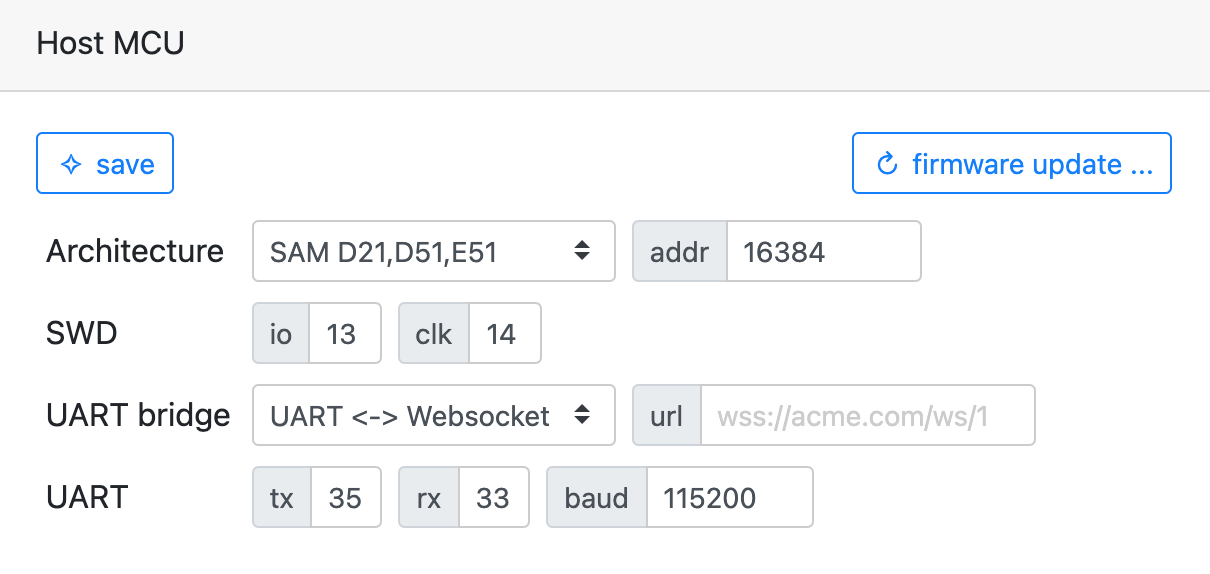
Configuration using API
The following console command performs the same setup as the GUI method above:
curl -su :API_KEY https://dash.vcon.io/api/v3/devices/ID/rpc/config.set \
  -d '{"config":{"host":{"arch":100,"mode":3,"uart":{"rx":33,"tx":35},"swd":{"io":13,"clk":14}}},"save":true,"reboot":500}'
In the command above, API_KEY is a cloud authentication key. It could be
copied from the UI dashboard. ID is the actual ID you're working with. It
can be taken from the UI dashboard.
See Configuration Reference for a detailed description of all configurable parameters.
Arduino Nano

Configuration using GUI
Once wiring is done, go to https://dash.vcon.io and select "action" → "Manage device" to configure the Host. This loads device management console with several different sections. Now we're interested in "Configuration" section. Change values to make it look like this and hit "save":
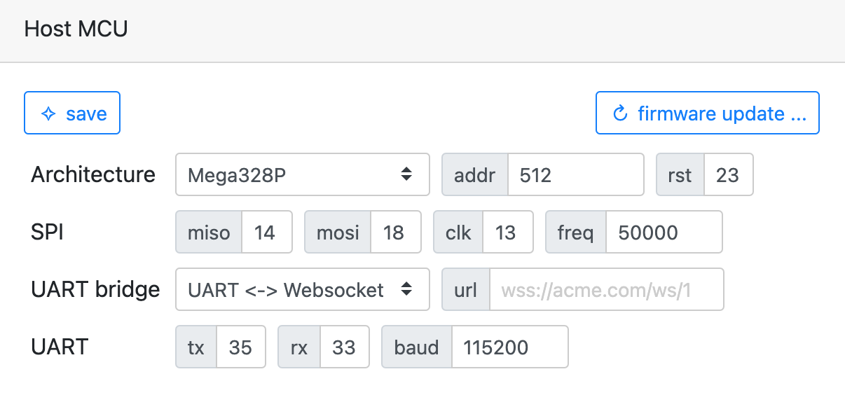
Configuration using API
The following console command performs the same setup as the GUI method above:
curl -su :API_KEY https://dash.vcon.io/api/v3/devices/ID/rpc/config.set \
  -d '{"config":{"host":{"arch":300,"mode":3,"uart":{"rx":33,"tx":35},"swd":{"io":13,"clk":14}}},"save":true,"reboot":500}'
In the command above, API_KEY is a cloud authentication key. It could be
copied from the UI dashboard. ID is the actual ID you're working with. It
can be taken from the UI dashboard.
See Configuration Reference for a detailed description of all configurable parameters.
Firmware update
A device firmware can be programmed by a simple HTTP API call:
curl -su :API_KEY https://dash.vcon.io/api/v3/devices/ID/ota --data-binary @firmware.bin
In the command above, API_KEY is a cloud authentication key. It could be
copied from the UI dashboard. ID is the actual ID you're working with. It
can be taken from the UI dashboard.
That command pushes new device firmware firmware.bin to the VCON module
attached to your device, and VCON module reprograms your device over the
programming pins. Note that the whole communication is authenticated, and
secured by the industry-standard TLS connection:

VCON module can also update itself, using the same cloud API. Just add an extra
?target=vcon query string to the ota endpoint, and send a VCON firmware,
not your MCU firmware:
curl -su :API_KEY https://dash.vcon.io/api/v3/devices/ID/ota?target=vcon --data-binary @vcon.bin
Serial monitor
A device's UART can be monitored by a simple HTTP API call:
curl -su :API_KEY https://dash.vcon.io/api/v3/devices/ID/tx?t=5
In the command above, API_KEY is a cloud authentication key. It could be
copied from the UI dashboard. ID is the actual ID you're working with. It
can be taken from the UI dashboard.
The t=5 parameter tells the number of seconds to monitor. When that time
is over, the command exits. If you want a longer monitor time, use some
larger value, for example t=9999.
VCON module can not only read, but also write to the device's UART:
curl -su :API_KEY https://dash.vcon.io/api/v3/devices/ID/rpc/serial.write -d '{"data": "hello"}'
curl -su :API_KEY https://dash.vcon.io/api/v3/devices/ID/rpc/serial.write -d '{"hex": "610d0a"}'
NOTE: a serial console is provided by the https://dash.vcon.io GUI.
Using remote serial read and write, it is easy to implement remote device control and automated device testing.
Management Cloud
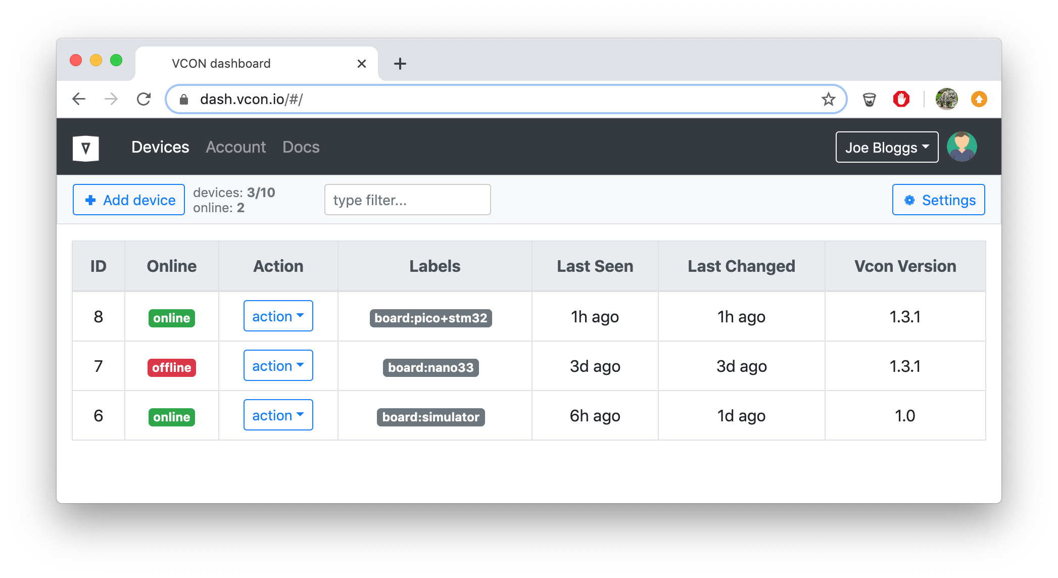
Overview
VCON cloud provides management API access to your devices, and an easy to use Web UI with device dashboard:
Authentication
Cloud API access can be authenticated via Basic authentication, where username is set to the empty string, and password is set to the API key string. The API key string can be copied from the GUI dashboard. The following table provides a summary:
| Example | |
|---|---|
| Programmatic | Add request header: Authorization: Bearer API_KEY |
| Command Line | curl -su :API_KEY https://dash.vcon.io/api/v3/devices |
Test account
The https://dash.vcon.io provides a test account with the following credentials:
| Password | API_KEY | |
|---|---|---|
| test | test | test |
It is open to everyone for demonstration purposes. Anyone can login to dash.vcon.io using test/test as an email/password. And below is an example of an API usage:
Get all devices registered under a test account:
curl -su :test https://dash.vcon.io/api/v3/devices
List all available functions of device 1:
curl -su :test https://dash.vcon.io/api/v3/devices/1/rpc/rpc.list
Call device 1, function sys.reboot:
curl -su :test https://dash.vcon.io/api/v3/devices/1/rpc/sys.reboot
Notifications
VCON cloud provides a special secure WebSocket endpoint
wss://dash.vcon.io/api/v3/notify. This is a read-only notifications endpoint.
Each notification is a JSON object with three keys:
name- a notification name, e.g.online,offline, and so ondid- an ID of a device that generated the eventdata- an optional notification-specific data.

Below is the list of the events:
{"name":"online","did":ID}- generated by the cloud when a device becomes online{"name":"offline","did":ID}- generated by the cloud when a device becomes offline{"name":"updated","did":ID,"data":{...}}- generated by the cloud when a device changes itsstateattribute{"name":"ble.adv","did":ID,"data":{...}}- generaged by the VCON module in the BLE bridge mode, whenble.mode=2. Thedatacontains BLE beacon data.{"name":"CUSTOM","did":ID,"data":CUSTOM}- a custom event that could be generated by a Host microcontroller in the RPC bridge mode. A Host micro must call thecloud.CUSTOMRPC function with anyparamsyou want. For example, this is how a Host microcontroller can send some sensor data:
jsonrpc_printf(fn, NULL, "{%Q:%Q,%Q:{%Q:%g}}",
               "method", "cloud.temperature",
               "params", "value", 123.456)
This call generates {"name":"temperature","did":ID,"data":{"value":123.456}}
NOTE: the cloud UI uses notification endpoint to catch device changes, like online/offline, and dispays that respectively. You can create your custom dashboard using cloud API and notifications.
You can catch all notifications sent by the cloud.
Below is a simple NodeJS application that catches all incoming notifications
and prints them on a console. Create file catcher.js, copy/paste the
folowing content:
const Websocket = require('ws');  // npm install -g ws
const addr = 'wss://dash.vcon.io/api/v3/notify?access_token=API_KEY';
const reconnect = function() {
  const ws = new Websocket(addr, {origin: addr});
  ws.on('error', msg => console.log('Got error:', msg.toString()));
  ws.on('message', msg => console.log('Got message:', msg.toString()));
  ws.on('close', () => setTimeout(reconnect, 1000));
};
reconnect();
Change API_KEY to your API key which could be copied from the "Account" tab in
the cloud UI. Run this file and see how arriving notifications are printed:
$ node catcher.js
Got message: {"name":"online","did":1}
NOTE: by bringing up a custom notification catcher, you can integrate with any other 3rd party service - for example, store data into a Google/AWS/Azure, dump data in your custom dashboard, send SMS, run analytics, et cetera.
Cloud API Reference
NOTE: URI in a table below must be prefixed with
https://dash.vcon.io/api/v3. Example API call that lists all devices registered by user:curl -su :API_KEY https://dash.vcon.io/api/v3/devices
| Method | URI | Description |
|---|---|---|
| GET | /user | Get user |
| POST | /user | Set user. Parameters: JSON object with new user data: {"fullname":"...", "company":"...", "email":"...", "address":"...", "phone":"...", "settings":{...}} |
| GET | /devices | Get device list |
| POST | /devices | Create new device. Parameters: none |
| GET | /devices/:id | Get device with ID :id |
| POST | /devices/:id | Update device with ID :id. Parameters: JSON object with device data: {"labels":{"board":"nano33"}, "state":{...}} |
| DELETE | /devices/:id | Delete device with ID :id |
| GET | /devices/:id/fs/:name | Get file :name on device :id |
| POST | /devices/:id/fs/:name | Write file :name on device :id. File data is the HTTP POST body, sent varbatim - e.g. using curl --data-binary |
| POST | /devices/:id/rpc/:name | Call RPC function :name on device :id. Parameters: none, or a JSON object specific to that RPC function. If no parameters are given, a GET request can be used too |
| POST | /devices/:id/ota | Update firmware over the air. By default, a Host MCU gets updated. If you want to OTA a VCON module, append ?target=vcon to the URL. HTTP body must be a raw .hex or .bin file data with a new firmware. Example: curl -su :test ttps://dash.vcon.io/api/v3/devices/42/ota?hex=1 --data-binary @PATH_TO_FIRMWARE.hex |
| GET | /devices/:id/bye | Disconnect device. If, for various reasons, a device gets stuck, force reconnection |
| GET | /devices/:id/tx?t=n | Capture serial output from device :id for n seconds. If t is not specified, it defaults to 5 |
RPC API Reference
The following table summarises built-in RPC functions that are exposed by a VCON module. These functions can be called remotely via REST, or locally via UART (for example, Host MCU can call any of the VCONs RPC function).
Example call that lists files on a module (module must be online):
curl -su :API_KEY https://dash.vcon.io/api/v3/devices/ID/rpc/fs.list
Some API calls require parameters, a JSON string in HTTP POST body:
$ curl -su :API_KEY https://dash.vcon.io/api/v3/devices/ID/rpc/fs.read -d "{\"file\":\"config.json\"}"
{"id":2,"result":{"file":"config.json","offset":0,"left":0,"data":"ewogICJ3aWZp..."}}
| Method | Parameters | Description |
|---|---|---|
| rpc.list | - | Show all RPC functions available |
| sys.info | - | Show general information about a device, like build timestamp, firmware version, uptime in seconds |
| sys.log | - | Show the current console log buffer. Every console log message is stored in a fixed-size, 1K buffer. New messages are appended to the end, older messages are removed to keep the space fixed. This RPC returns the log buffer and cleans it. Call this function repeatedly to get devices's console log |
| sys.reboot | - | Reboot device |
| config.get | - | Show devices configuration |
| config.set | |
Update device configuration. config attribute specify configuration changes. save is an optional parameter (default false) that tells to make changes permanent by storing them in a config.json file on a device. Note: config.json file keeps only configuration overrides. If you set configuration option to its default value, it disappears from the "config.json" file |
| gpio.write | |
Set a given VCON pin to a given value |
| gpio.read | |
Read a given VCON pin |
| fs.list | - | List files on VCON filesystem |
| fs.read | |
Get file data from given offset. Returned file data is base64-encoded |
| fs.write | |
Write data to a file. Data must be base64-encoded. Data is appended to the end of the file. A written file gets truncated before write, unless an optional append parameter is set to true (it is false by default) |
| swd.exec | |
Send a list of SWD commands to the Host MCU. Available SWD commands:rst - send SWD reset sequenceinit - reset and initrd0,rd1,rd2,rd3 - read debug registerwd0,wd1,wd2 - write debug registerra0,ra1,ra2,ra3 - read access registerwa0,wa1,wa2,wa3 - write access registerrm,ADDR - read memory at ADDR (hex)rm,ADDR,MASK,VAL - read memory at ADDR until MASK equals to VALwm,ADDR,VAL - write memoryNote: ADDR, VAL, MASK values must be lowercase hexadecimal numbers without the 0x prefix, e.g.: 2ef. Example - a standard MCU init sequence is rst rd0 wd0,1f wd2,0 wd1,50000f00 wa0,23000012 rR - read registerswR,HEX1,HEX2,.. - write registers |
| swd.read | |
Read Host MCU memory over SWD |
| swd.write | |
Write to the Host MCU memory over SWD. Data is a hex-encoded buffer to write. |
| mcu.reset | - | Reset Host MCU |
| serial.write | |
Write data to the serial port. One of the data (string to send), or hex (hex encoded data), or base64 (base64 encoded data) should be present |
| spi.exec | |
Execute SPI transaction on Host MCU. $host.spi must be configured. COMMANDS is a space-separated list of SPI commands which has format ADDRESS HEX_WRITE.READ_SIZE. For example, reading AVR fuses is the following command: ac530000.04 50000000.04 58080000.04 50080000.04 |
| wifi.scan | - | Scan WiFi and return a list of available WiFi networks |
| host.* | any | Forward RPC frame to the Host MCU, stripping host. prefix from method name |
| cloud.* | any | Forward RPC frame to the cloud, stripping cloud. prefix from method name. Use this RPC to send custom notifications to the cloud. The following method names are treated specially by the cloud:{"method":"cloud.state.set","data":...} - This notification changes device's state attribute on the cloud. The behavior is similar to AWS/Azure device shadow - setting an attribute touches only that attribute and leaves the rest intact. To delete an attribute, set it to null |
VCON module
Configuration Reference
VCON module configuration is a JSON string. It is stored on the root filesystem
in "config.json" file. It could be viewed by calling config.get RPC function:
curl -su :API_KEY https://dash.vcon.io/api/v3/devices/ID/rpc/config.get
{"wifi":{"sta":{"ssid":"MyWiFiNetwork","pass":"mypassword"}},"dash":{...},...}
In order to change one or more configuration option, call config.set RPC function and pass
a JSON object with 2 parameters: required config with your changes, and optional
boolean save to save your changes to "config.json".
For example, this command changes an architecture of Host microcontroller to
200 (STM32 with 1k flash pages), and saves:
curl -su :API_KEY https://dash.vcon.io/api/v3/devices/ID/rpc/config.set -d "{\"config\":{\"host\":{\"arch\":200}},\"save\":true}"
NOTE: in order to restore the default value for any option, set it to
null.
The following table describes all configuration options. Every option name is specified by its JSON path.
| Name | Type | Description |
|---|---|---|
| $.wifi.mode | int | WiFi mode. Default: 1 (enabled). Possible values: 0 - disabled, 1 - enabled |
| $.wifi.sta.ssid | string | WiFi network name. Default: "" (unset) |
| $.wifi.sta.pass | string | WiFi network password. Default: "" (unset) |
| $.wifi.ap.ssid | string | WiFi Access Point name for an unconfigured device . Default: "vcon-????". Note: ? characters in the AP name will be replaced with the MAC address hex values |
| $.dash.url | string | Cloud address. Default: "wss://dash.vcon.io/api/v3/rpc". Override it if you have a dedicated/private cloud instance |
| $.dash.pass | string | Device cloud auth token. Default: "" (unset) |
| $.debug.level | string | Console log level. Default: "2". Possible values: "0" - disable console log "1" - log errors only "2" - log errors and info messages "3" - log erros, info and debug messages "4" - log everything Per-file overrides are supported, e.g. "2,tcp:3" |
| $.debug.tlslevel | int | Console log level for TLS. Default: 1. Possible values: 0-5 |
| $.debug.udpaddr | string | UDP log address "IP:PORT". Default: "". If set, then console log messages are also sent to the specified HOST:PORT |
| $.mqtt.url | string | MQTT server URL. Required only when $.host.mode is 2. Default: NULL (not set). The format of the URL is PROTO://USER:PASS@HOST:PORT, where PROTO is mqtt or mqtts, USER and PASS are MQTT credentials (could be omitted). NOTE: VCON sets MQTT client ID equal to the $.device.id |
| $.mqtt.rx | string | MQTT topic for VCON to subsribe to. All data read from this topic, VCON will forward to the Host MCU UART RX |
| $.mqtt.tx | string | MQTT topic for VCON to publish to. All data VCON reads from the Host MCU UAET, VCON publishes to that topic |
| $.mqtt.cert | string | Client TLS certificate file name. Required only for 2-way TLS. Must be prefixed with /spiffs, e.g. /spiffs/my_cert.pem |
| $.mqtt.key | string | Client TLS certificate key file name. Required only for 2-way TLS. Must be prefixed with /spiffs, e.g. /spiffs/my_key.pem |
| $.tcp.url | string | Remote TCP server URL. Example: udp://1.2.3.4:1234, or tcp://foo.com:1234. Required only when $.host.mode is 4. Default: NULL (not set) |
| $.tcp.port | int | Local TCP server port. Default: 0 (TCP listener is not started). If the value is >0, then VCON starts a TCP listener to exchange data with UART. Only a single connection is allowed, and a new connection terminated the previous one. |
| $.ws.url | string | Websocket server URL. Required only when $.host.mode is 3. Default: NULL (not set) |
| $.ws.hdrs | string | Websocket extra HTTP headers for WS handshake. Required only when $.host.mode is 3. Default: NULL (not set). Example: Authorization: Bearer foobar\r\n |
| $.ws.cert | string | Client TLS certificate file name. Required only for 2-way TLS. Must be prefixed with /spiffs, e.g. /spiffs/my_cert.pem |
| $.ws.key | string | Client TLS certificate key file name. Required only for 2-way TLS. Must be prefixed with /spiffs, e.g. /spiffs/my_key.pem |
| $.device.id | string | An arbitrary device identification. Used only in the BLE adv forwarding, and passed as a gw BLE adv frame parameter |
| $.device.dns | string | Custom DNS server URL. Example: udp://1.1.1.1:53 - which is a CloudFlare DNS server. A special value "dhcp" fetches DNS setting from the DHCP. Default: "" (unset), in which case Google's udp://8.8.8.8:53 is used |
| $.device.sntp | string | Custom SNTP server URL. Example: udp://time.microsoft.com:123. A special value "dhcp" fetches SNTP setting from the DHCP. Default: "" (unset), in which case Google's time serverudp://time.google.com:123 is used |
| $.rpc.safe | string | List of comma-separated RPC functions available to Host MCU, and over the HTTP server. Default: config.set,sys.*,rpc.*,gpio.*,cloud.* |
| $.host.arch | int | A Host MCU arhitecture. Default: 0 (unset). Required for reprogramming. Possible values: 100 - Microchip SAMD200 - STM32 with 1k flash pages201 - STM32 with 2k flash pages202 - STM32 with 16,16,16,16,64,128,128,128k pages203 - STM32 with 32,32,32,32,128,256,256,256k pages 204 - STM32 with 8k pages 300 - AVR (e.g. classic Arduinos) |
| $.host.rst | int | VCON pin to which Host MCU's RESET pin is connected. Default: -1 (unset). Required for reprogramming / rebooting an attached MCU if that cannot be done via SWD, for example for attached AVR |
| $.host.mode | int | Host MCU communication mode. Default: 0 (disabled). Possible values:0 - disabled1 - RPC bridge. Serial link is exchanging JSON-RPC frames, delimited by newline characters. Make sure to set $.uart.delim to 1 2 - transparent bridge. Serial data is uninterpeted, sent to/from connected $.tcp, $.mqtt, $.ws endpoint as one-to-many. If $.uart.delim=0, then data is sent as-is. If $.uart.delim is 1 or 2, then data is buffered until newline, and only then sent (wihout the newline). |
| $.host.addr | int | Flash memory address for .bin firmwares. For .hex firmwares, this value is ignored. Default: 0 |
| $.swd.io | int | VCON pin to which Host MCU's SWDIO pin is connected. Default: -1 (unset). Required for reprogramming ARM MCUs |
| $.swd.clk | int | VCON pin to which Host MCU's SWDCLK pin is connected. Default: -1 (unset). Required for reprogramming ARM MCUs |
| $.swd.dur | int | SWD clock duration in VCON's nop instructions. Default: 50 |
| $.uart.tx | int | VCON pin to which Host MCU's UART TX pin is connected. Default: -1 (unset) |
| $.uart.rx | int | VCON pin to which Host MCU's UART RX pin is connected. Default: -1 (unset) |
| $.uart.cts | int | VCON pin to which Host MCU's UART CTS pin is connected. Default: -1 (unset) |
| $.uart.rts | int | VCON pin to which Host MCU's UART RTS pin is connected. Default: -1 (unset) |
| $.uart.baud | int | A Host MCU's UART baud rate. Default: 115200 |
| $.uart.delim | int | UART datagram delimiter. Default: 0. Possible values:0 - Data from/to UART are sent immediately. 1 - data is newline delimited. VCON buffers UART data until newline is found, and only then sends it. The buffer size is 2048 bytes, so do not send datagrams larger than that. 2 - Data is newline delimited, and CRC32 data checksum is added before the newline |
| $.uart.crc | int | CRC32 verification for the datagrams. Default: 0 (disabled). If enabled, VCON expects 8-char hex CRC32 before the delimiter for outbound datagrams, and adds a 8-char CRC32 for inbound datagrams. Datagrams with wrong CRC are silently dropped |
| $.i2c.sda | int | VCON pin to which Host MCU's I2C SDA pin is connected. Default: -1 (unset) |
| $.i2c.clk | int | VCON pin to which Host MCU's I2C SCK pin is connected. Default: -1 (unset) |
| $.spi.mosi | int | VCON pin to which Host MCU's SPI MOSI pin is connected. Default: -1 (unset) |
| $.spi.miso | int | VCON pin to which Host MCU's SPI MISO pin is connected. Default: -1 (unset) |
| $.spi.clk | int | VCON pin to which Host MCU's SPI CLK pin is connected. Default: -1 (unset) |
| $.spi.freq | int | Host MCU's SPI clock frequency. Default: 50000 |
| $.ble.mode | int | BLE gateway mode. Default: 0 (disabled). Possible values:0 - BLE disabled1 - BLE enabled, configurator is starged2 - BLE enabled. Beacon data is forwarded to the cloud as a ble.adv notification. NOTE: this mode disables BLE device configurator 3 Beacon data is forwarded to the $.mqtt.tx topic of the configured MQTT server. NOTE: this mode disables BLE device configurator |
| $.ble.filter | string | A comma separated list of glob patterns. BLE advertisements whose MAC addresses or names do not match all patterns, are ignored. Default: empty, which means all BLE advertisements match. Example: MyName*,aabbcc* - match devices whose names start with MyName or MAC address start with aabbcc |
| $.ble.lowat | int | A RAM threshold. If free RAM is lower than this value, then ignore an incoming BLE advertisement, do not forward it to the cloud to preserve RAM. Default: 0 |
| $.eth.mode | int | Ethernet mode. Default: 0 (disabled). Possible values:0 - Ethernet disabled1 - Ethernet enabled |
| $.eth.addr | int | Ethernet PHY address. Default: 0 |
| $.eth.mdc | int | Ethernet EMAC MDC pin. Default: -1 (unset) |
| $.eth.mdio | int | Ethernet EMAC MDIO pin. Default: -1 (unset) |
| $.eth.phy | int | Ethernet PHY. Possible values:0 - LAN87201 - IP1012 - RTL82013 - DP838484 - KSZ80xx5 - W5500 (SPI)6 - DM9051 (SPI)7 - KSZ8851SNL (SPI)Default: -1 (unset) |
| $.eth.irq | int | Ethernet interrupt pin of the SPI chip. Default: -1 (unset) |
| $.pins.status | int | Status LED pin. Default: -1 (unset). If set, it is assumed that is an LED, and does the following:fast 75 ms blink - when network is not connected, slow 750 ms blink - when network is connected, but cloud is not, steady light - when cloud is connected |
| $.pins.factory | int | Factory reset pin. Default: -1 (unset). If set, it is assumed that this pin is connected to a pulled-up button. Pressing this button for more than 3 seconds (pulling low) triggers factory reset, which copies factory.json to `config.json |
ESP32 Pinout Reference
- R column (reset state)
- 0: input disabled
- 1: input enabled
- 2: input enabled, pull down
- 3: input enabled, pull up
- Strapping pins:
- 0: high - boot from flash, low - enter boot loader mode
- 2: low when pin 0 is low
- 12: if high, boot fail
- 15: if low, boot messages are not printed
- N column (special notes): R: RTC/Analog, I: Input Only
- Colors: strapping, internal flash, input only
| Pin | F1 | F2 | F3 | F4 | F5 | R | N |
|---|---|---|---|---|---|---|---|
| 0 | GPIO0 | CLK_OUT1 | - | - | ETH_TX_CLK | 3 | R |
| 1 | U0TXD | CLK_OUT3 | - | - | ETH_RXD2 | 3 | - |
| 2 | GPIO2 | HSPIWP | HS2_DATA0 | SD_DATA0 | - | 2 | R |
| 3 | U0RXD | CLK_OUT2 | - | - | - | 3 | - |
| 4 | GPIO4 | HSPIHD | HS2_DATA1 | SD_DATA1 | ETH_TX_ER | 2 | R |
| 5 | GPIO5 | VSPICS0 | HS1_DATA6 | - | ETH_RX_CLK | 3 | - |
| 6 | SD_CLK | SPICLK | HS1_CLK | U1CTS | - | 3 | - |
| 7 | SD_DATA_0 | SPIQ | HS1_DATA0 | U2RTS | - | 3 | - |
| 8 | SD_DATA_1 | SPID | HS1_DATA1 | U2CTS | - | 3 | - |
| 9 | SD_DATA_2 | SPIHD | HS1_DATA2 | U1RXD | - | 3 | - |
| 10 | SD_DATA_3 | SPIWP | HS1_DATA3 | U1TXD | - | 3 | - |
| 11 | SD_CMD | SPICS0 | HS1_CMD | U1RTS | - | 3 | - |
| 12 | MTDI | HSPIQ | HS2_DATA2 | SD_DATA2 | ETH_TXD3 | 2 | R |
| 13 | MTCK | HSPID | HS2_DATA3 | SD_DATA3 | ETH_RX_ER | 2 | R |
| 14 | MTMS | HSPICLK | HS2_CLK | SD_CLK | ETH_TXD2 | 3 | R |
| 15 | MTDO | HSPICS0 | HS2_CMD | SD_CMD | ETH_RXD3 | 3 | R |
| 16 | GPIO16 | - | HS1_DATA4 | U2RXD | ETH_CLK_OUT | 1 | - |
| 17 | GPIO17 | - | HS1_DATA5 | U2TXD | ETH_CLK_180 | 1 | - |
| 18 | GPIO18 | VSPICLK | HS1_DATA7 | - | - | 1 | - |
| 19 | GPIO19 | VSPIQ | U0CTS | - | ETH_TXD0 | 1 | - |
| 21 | GPIO21 | VSPIHD | - | - | ETH_TX_EN | 1 | - |
| 22 | GPIO22 | VSPIWP | U0RTS | - | ETH_TXD1 | 1 | - |
| 23 | GPIO23 | VSPID | HS1_STROBE | - | - | 1 | - |
| 25 | GPIO25 | - | - | - | ETH_RXD0 | 0 | R |
| 26 | GPIO26 | - | - | - | ETH_RXD1 | 0 | R |
| 27 | GPIO27 | - | - | - | ETH_RX_DV | 0 | R |
| 32 | 32K_XP | - | - | - | - | 0 | R |
| 33 | 32K_XN | - | - | - | - | 0 | R |
| 34 | VDET_1 | - | - | - | - | 0 | RI |
| 35 | VDET_2 | - | - | - | - | 0 | RI |
| 36 | S_VP | - | - | - | - | 0 | RI |
| 37 | S_CAPP | - | - | - | - | 0 | RI |
| 38 | S_CAPN | - | - | - | - | 0 | RI |
| 39 | S_VN | - | - | - | - | 0 | RI |
BLE gateway
In the BLE bridge mode, VCON module receives BLE beacon advertisements from nearby BLE beacons, and forwards them to the cloud as device notifications. You can catch those notifications by using a notification catcher, and do whatever you want with the data - store in a database, do real-time processing, etc.
Also VCON provides a BLE.Advertise RPC function, which you can call
from anywhere via the cloud and trigger VCON module to send a BLE advertisement
with configurable payload.
To configure BLE bridge, see ble section in the
Configuration Reference.
Troubleshooting
If any quick start guide step fails, or the VCON module behaves in an unexpected way, please follow these steps:
- Attach a serial console to the ESP32 (ERX and ETX pins)
- Physically power cycle the device
- Post a message using a contact form with the following:
- Which hardware you're using
- Which guide you are following
- Which exactly step (or command) fails, include the command and an output
- The full console log, including all boot messages
Recipes
Live debug with GDB
If a target microcontroller is ARM, and SWD pins are wired to the VCON
module, it is possible to debug it remotely using gdb. The trick is
to run a simple Node.JS application which implements a GDB server, and
translates GDB commands to the SWD RPC commands to the target device connected
to dash.vcon.io. Here is the sequence of actions:
Step 2. Install required NPM packages. Open terminal/command prompt and execute:
$ npm i -g ws
Step 2. Download vcon-gdb-server.js.
Open terminal/command prompt and execute (take API_KEY from the
https://dash.vcon.io. DEVICE_ID is the device number you want to debug):
$ node vcon-gdb-server.js API_KEY DEVICE_ID
Started GDB server at port 2424
Step 3. Start gdb. Open terminal/command prompt and execute (change firmware.elf to the actual file name of your firmware):
$ arm-none-eabi-gdb -q -ex 'set confirm off' \
                       -ex 'set remotetimeout 10' \
                       -ex 'target remote localhost:2424' \
                       firmware.elf
Reading symbols from firmware.elf...
Remote debugging using localhost:2424
Reset_Handler () at cmsis_h7/Source/Templates/gcc/startup_stm32h743xx.s:61
61	  ldr   sp, =_estack      /* set stack pointer */
(gdb) mon reset halt
(gdb) b main
Breakpoint 1 at 0x8000418: file hal.h, line 94.
(gdb) c
Continuing.

Breakpoint 1, main () at hal.h:94
94	  gpio_init(pin, GPIO_MODE_OUTPUT, GPIO_OTYPE_PUSH_PULL, GPIO_SPEED_HIGH,
(gdb)
Send data to MQTT
The commumication chip can be configured to read the serial output of the Host MCU and forward all data to the MQTT server of your choice. That is called a "UART-MQTT bridge mode". In order to enable that,
Step 1. Login to https://dash.vcon.io, make sure your device is online, choose "action" → "Manage device"
Step 2. In the Configuration section, enable "expert view". Edit the configuration JSON, "mqtt" section:
  ...
  "mqtt": {
    "rx": "vcon/rx",
    "tx": "vcon/tx",
    "url": "mqtt://broker.hivemq.com:1883"
  },
  ...
Step 3. In the Configuration section, set $.host.mode to 2:
  ...
  "host": {
    "mode": 2,
  ...
Step 4. Click on "save" button, wait until device reboots
That's it! Now all data that is printed to the serial, gets forwarded to the
topic vcon/tx of the MQTT server broker.hivemq.com:1883. Feel free to choose
a different topic or server address.
Note there is an rx topic, too. You've guessed it: everything that is sent
to that MQTT topic, a communication chip catches and sends to the Host MCU
serial line, so MQTT/Serial communication is bi-directional.
NOTE: on Arduino framework, Serial on VCON-328 and Serial1 on VCON-D51.
Connect to AWS IoT
Below is a detailed step-by-step guide on how to enable VCON module to connect to AWS IoT and forward UART data to/from the specified MQTT topics.
- Create a permissive IoT policy:
- Login to AWS IoT console
- On the left bar, click on "Policies"
- On the right pane, click on "Create"
- Fill in fields in the following way and click "Create":
- Name: Policy1, Action: iot:*, Resource ARN: *, Effect: allow

- Register AWS IoT thing
- On the left bar, click on "Manage" → "Things"
- On the right pane, click on Create things → Create single thing → Next
- Enter thing name, for example "thing1", click "Next"
- Choose "Auto-generate new certificate", click "Next"
- Chooae policy "Policy1", click "Create thing"
- Download certificate files#
- In the dialog box that appears, download all three generated certificates:

- Rename xxx-certificate.pem.crt to cert.pem
- Rename xxx-private.pem.key to key.pem
- Upload cert.pem and key.pem to VCON
- Login to VCON dashboard, select your device → Manage
- In the File Manager section, click on "upload" button
- Upload two files, cert.pem and key.pem
- Modify MQTT configuration
- In the Configuration section, click on "expert view", search for "mqtt" section
- Fill MQTT section as follows (note, to find out
YOUR_AWS_IOT_ENDPOINT_URL, click on "Settings" link on the AWS IoT console left bar and copy the "Endpoint" URL on the right pane):
"mqtt": {
  "url": "mqtts://YOUR_AWS_IOT_ENDPOINT_URL:8883",
  "rx": "vcon/rx",
  "tx": "vcon/tx",
  "cert": "/spiffs/cert.pem",
  "key": "/spiffs/key.pem",
  "hexdump": 0
},
- Click save. Wait until your device reboots and becomes online
- Configure UART / MQTT bridge
- Refresh your device manager view. The "expert" view should become unchecked now
- In the UART bridge, select "UART <-> MQTT"
- Fill in UART rx and tx pins of your Host MCU
Send data to anything
What if you want to send data to something that is not MQTT - for example, to a custom server, or to a database like Influx? That is also possible. When a communication chip reads Host MCU serial, it generates a notification on the management cloud. It is possible to intercept that notification, and have a custom code to forward data to any destination.
Read the Notifications section for exact details.
Remote control - simple
An easy remote control via MQTT could be implemented by the "Send data to MQTT" recipe. Configure your RX and TX topics, MQTT server, then send data to the TX topic.
Use a simple Arduino sketch to read Serial to turn an LED on or off:
// IMPORTANT! On VCON-D51, use Serial1 instead of Serial
void setup() {
  Serial.begin(115200);
  pinMode(LED_BUILTIN, OUTPUT);
}

void loop() {
  if (Serial.available() > 0) {
    int character = Serial.read();
    if (character == '0') digitalWrite(LED_BUILTIN, LOW);  // '0' switches LED off
    if (character == '1') digitalWrite(LED_BUILTIN, HIGH); // '1' switches LED on
  }
}
Of course, the serial message format in this simple example is trivial. It is done for demonstration purposes. You could implement any format you wish, test it on a local serial monitor, then it is going to work the same way when you send commands over MQTT.
Keep it simple, though.
Remote control - advanced
When a communication chip is in Serial/MQTT bridge mode, a Host MCU is not aware it is connected to the Internet. It "thinks" that it is controlled via Serial, but in fact, serial data comes from the internets. A communication chip is, so to say, transparent, invisible to the Host MCU.
It is possible to put communication chip into an RPC mode. In this mode, a communication chip expects data to be in a JSON-RPC format: each chunk of data must be a JSON-RPC frame, separated by a newline character. This way, a communication chip is not transparent to the Host MCU: Host MCU knows it is there, it could send JSON-RPC requests to it and receive responses.
In RPC mode, a Host MCU can register any number of custom handler functions,
like GetStatus, SwitchOnMotor, or whatever is required. A communication
chip can bridge these to the management cloud, and any function could be
called via a familiar REST API.
Read RPC section below for a detailed explanation and an example sketch.
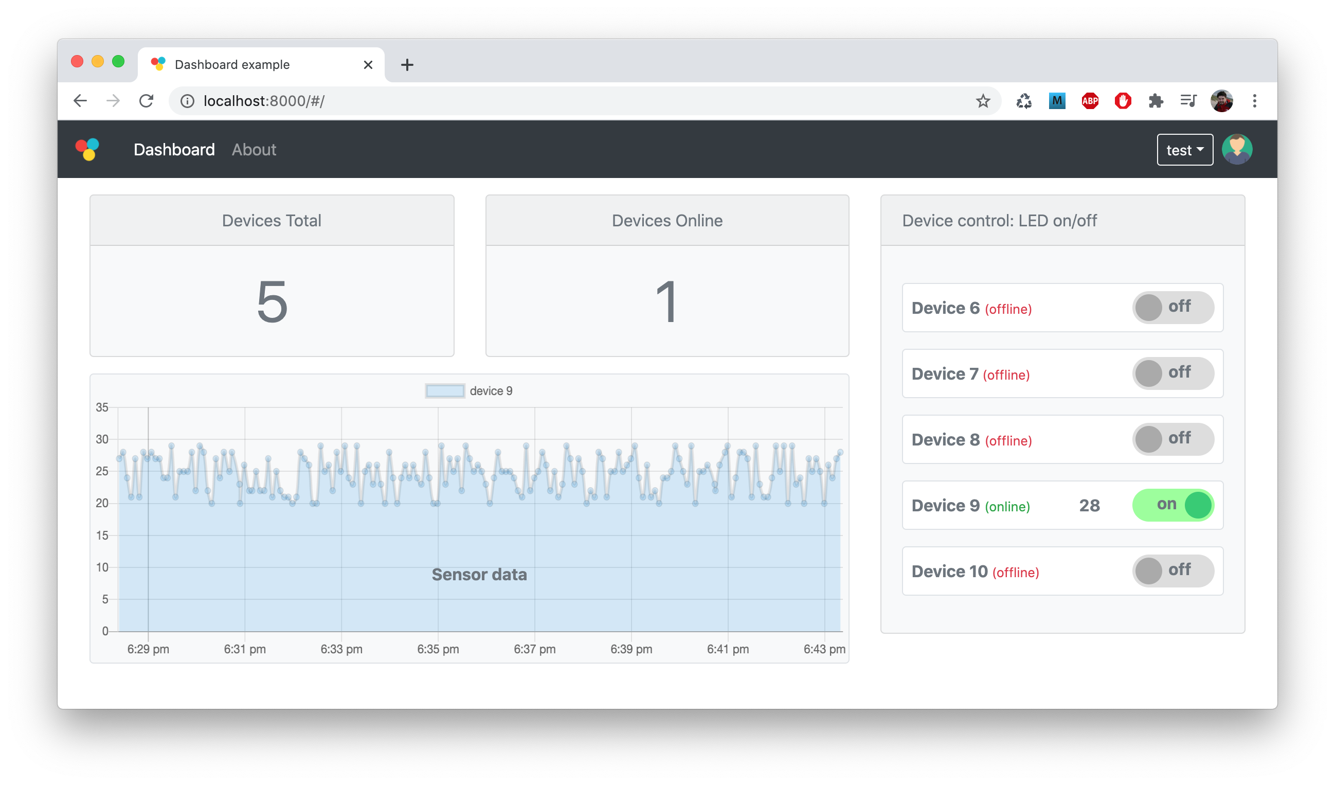
Complete dashboard
This recipe demonstrates how to build a complete custom monitoring dashboard using VCON platform. The implementation is very compact, well commented, and is designed to be a reference implementation of the production system. It consists of the following parts:
- A device, which
- can be controlled remotely by switching LED on or off
- sends data to the cloud that simulates sensor readings
- A custom dashboard, which
- is authenticated, requires users to log in
- stores sensor data in a local database (to a JSON file for simplicity)
- could be modified, and hosted anywhere - on a development laptop or on online hosting platform like AWS. The dashboard looks like this:
The overall architecture of such setup is as follows:

Step 1. Follow Quick Start Guide to register a VCON device on a dash.vcon.io management dashboard
Step 2. Clone or download the https://github.com/cesanta/vcon-app-example repository to your workstation
Step 3. Flash the firmware/firmware.ino sketch to your VCON device
using remote OTA.
This sketch implements a simple LED control and simulates periodic sensor data upload:
void setup() {
  Serial.begin(115200);
  pinMode(LED_BUILTIN, OUTPUT);
}

void loop() {
  // Handle serial input: switch LED on/off
  if (Serial.available() > 0) {
    int ch = Serial.read();
    if (ch == '0') digitalWrite(LED_BUILTIN, LOW);   // '0' switches LED off
    if (ch == '1') digitalWrite(LED_BUILTIN, HIGH);  // '1' switches LED on
  }

  // Print current status to serial every 5 seconds
  // A status message is a JSON string like this: {"led": 0, "sensor": 27}
  static unsigned long prev;
  unsigned long curr = millis();
  if (curr - prev > 5000) {
    char buf[100];
    snprintf(buf, sizeof(buf), "{\"led\": %d, \"sensor\": %d}",
             (int) digitalRead(LED_BUILTIN), (int) random(20, 30));
    Serial.println(buf);
    prev = curr;
  }
}
Step 4. Install Node.js, or skip this step if you have it installed
Step 5. Install ws node package for Websocket support:
$ npm i -g ws
Step 6. Edit backend/config.json file, change vcon_api_key value
and save the file. You can get you API key by logging to https://dash.vcon.io
dashboard on the Account page.
Step 4. Run your backend
$ node backend/main.js
That's it! Now point your browser to https://localhost:8000 and login as test/test. Here are the links for the core pieces of functionality:
- frontend/js/app.js - the frontend code for this dashboard, written in Preact
- backend/main.js - the backend code, written in Node.js
- firmware/firmware.ino - the Arduino firmware code
Here are some possible choices for where you can host your custom node.js backend, once the customisation is complete:
| Service | Price from | Payment type |
|---|---|---|
| https://www.heroku.com/ | 0 | usage based, with freebie quota |
| https://aws.amazon.com/ | 0 | usage based, with freebie quota |
| https://cloud.google.com/ | 0 | usage based, with freebie quota |
| https://azure.microsoft.com/ | 0 | usage based, with freebie quota |
| https://www.digitalocean.com/ | $5 / month | fixed price, run on a virtual instance |
Calling VCON RPC
A simplest way to use VCON is to set $.host.mode parameter to a MQTT or
Websocket bridge (2 or 3 respectively). In this case, everything that
Host MCU sends UART, VCON catches and sends over to a remote server.
VCON does not interpret UART data in any way, so the bridge is transparent.
However, if $.host.mode is set to 1 (RPC bridge), then VCON interprets
UART data that Host MCU sends as JSON-RPC commands. VCON module exports
many RPC methods (see RPC reference below), therefore Host MCU can call them
and utilise additional functionality VCON offers - like, reading/writing
files on VCON module, send HTTP requests to remote servers, etc.
Note that not all available RPC methods are exported via UART by default.
Available methods are controlled by the $.rpc.safe configuration setting,
see configuration reference below. Set $.rpc.safe to * to allow all
methods. Note: for production, tighten that up, because methods allowed by
$.rpc.safe are available over UART and BLE.
So, in this recipe, Host MCU periodically calls rpc.list RPC function
that lists methods available for Host MCU to call. The Arduino sketch is
for VCON-D51, or any other hardware setup where Serial is wired to the
serial console, and Serial1 to the VCON.
Step 1. Follow Quick Start Guide to register a VCON device on a dash.vcon.io management dashboard
Step 2. When you device is online on dash.vcon.io, choose
action → Manage device. In the FileSystem section, choose config.json
file. Add "rpc": {"safe": "*"}, right after the
first opening { at the beginning of the file. Change $.host.mode from 2 to 1.
Click Save. Click "reboot device" in the "General Information" section.
Step 3. Open Arduino IDE, Tools → Manage Libraries, search for msjon
and install mjson library.
Step 4. Create a new sketch. If you use VCON-D51, choose Adafruit ItsyBitsy M4 as a board. Copy-paste the following code: using remote OTA.
// Example firmware that calls VCON RPC function
// Set $.host.mode to 1 in the VCON configuration
#include <mjson.h>

int fn(const char *buf, int len, void *userdata) {
  return Serial1.write(buf, len);
}

int response_callback(const char *buf, int len, void *userdata) {
  Serial.write("Got response: ");
  Serial.write(buf, len);
  Serial.println();
  return len;
}

void setup() {
  Serial1.begin(115200);
  Serial.begin(115200);
  jsonrpc_init(response_callback, NULL);
}

void loop() {
  char buf[800];
  if (Serial1.available() > 0) {
    int len = Serial1.readBytes(buf, sizeof(buf));
    jsonrpc_process(buf, len, fn, NULL, NULL);
  }

  // Call RPC function every 3 seconds
  static unsigned long old;
  unsigned long now = millis();
  if (old > now || old + 3000 < now) {
    old = now;
    mjson_printf(fn, NULL, "{%Q:%d,%Q:%Q,%Q:{}}\n", "id", 1, "method", "rpc.list", "params");
  }
}
Step 5. Update Host MCU remotely. Open Serial console. You should see
messages printed periodically by the response_callback() function, that
shows a list of available RPC functions.
Congratulations! Now you know how to call any VCON RPC method from a Host MCU. See RPC reference below for a detailed description of each method.